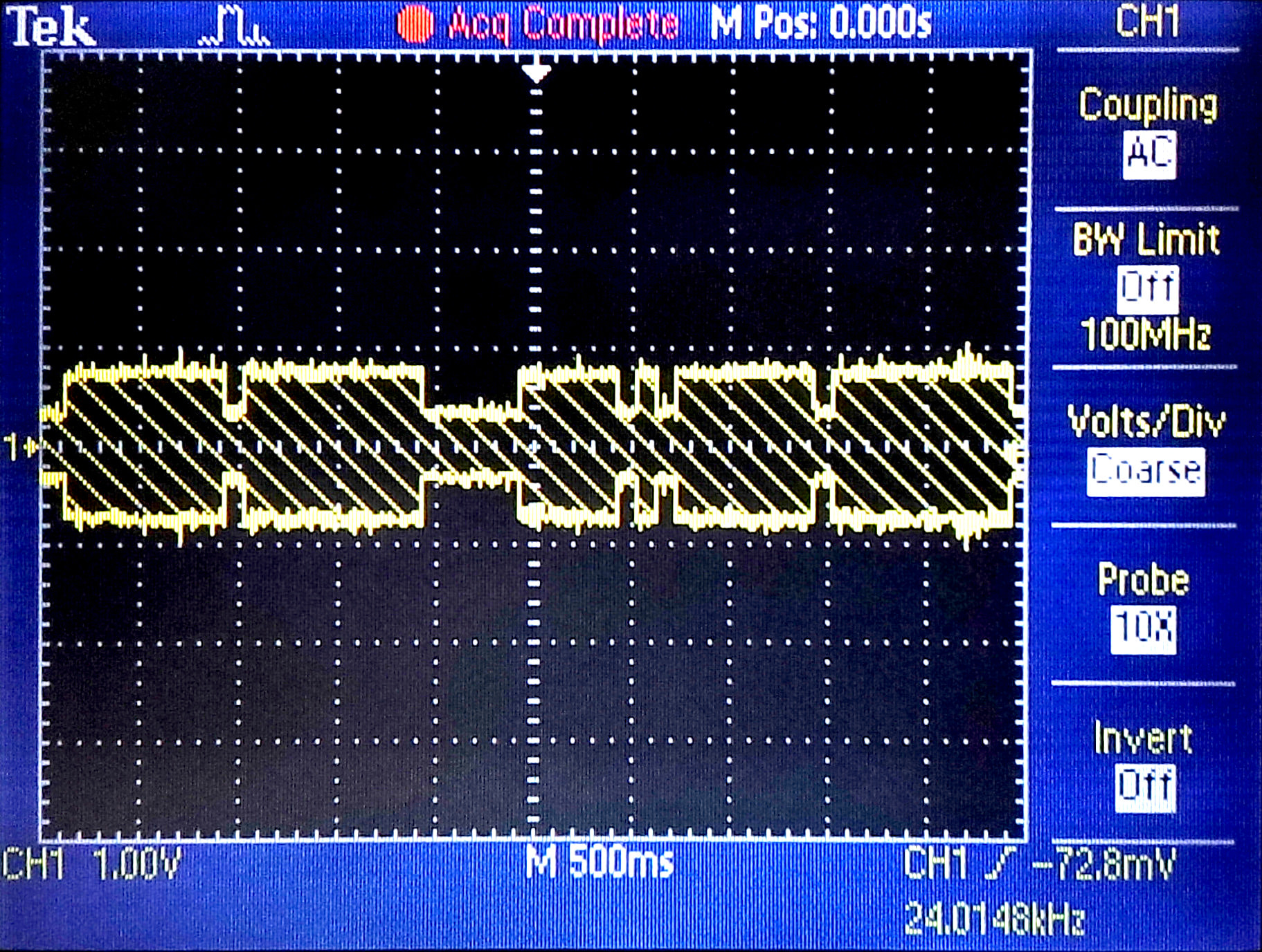
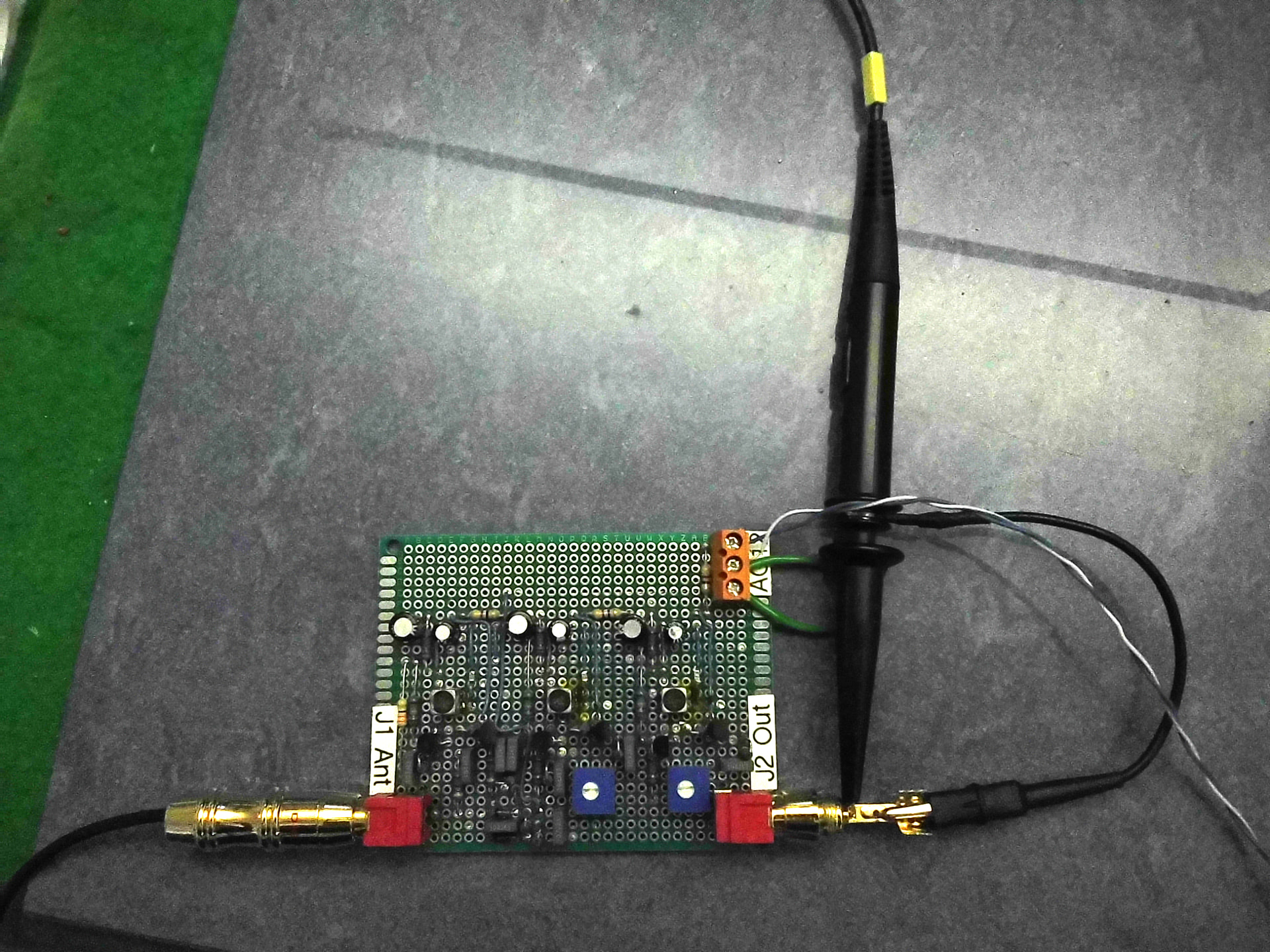
I’ve been working on a radio clock / frequency standard receiver for a while and yesterday I got to the milestone of receiving my first transmissions!
After a lot of looking around I decided to try to build the project in the January 1994 issue of 73 magazine.
It looked to be one of the simplest designs and was modular enough that I could understand it and build/test it in sections. I don’t have much (any) RF experience so I didn’t realise how tricky those regenerative receiver architectures can be but, luckily for me, that wasn’t the bit I had trouble with!
Initially I couldn’t find any variable inductors of the specified value so I got some fixed ones and tried wrapping extra turns. This didn’t work out too well and in the end I recalculated the tuned RF tank circuit capacitors based on variable coils that I could get.
This worked out well but I still had a lot of trouble with noise and interference. My receiver was absolutely swamped and I was getting huge but useless signals out of the RF amplifier.
As I switched off devices around the workshop things got better. First a computer monitor, then another and eventually the whole computer desk. One of the monitors was modulating huge bursts of noise at 200Hz onto the 60kHz carrier and the signal I was looking for was lost.
So far I’ve built the antenna, the antenna pre-amp and the RF amp. Next up is the AGC (Automatic gain control) amp and then some kind of decoder of my own design for the time data. I might also make the frequency reference that the author details in part 3 of the 73 magazine series.
This project can be re-tuned for most of the low-frequency radio clock stations around the world so if you’re interested in such things, check it out and let me know if you need any tips. I don’t know much but I can give you the benefit of my experience so far! I did my own protoboard layouts so I can let you have those as well.
That looks like a great project! And I’m glad you’re having some success!
Your build looks pretty clean but it might be susceptible to picking up noise… If you think it might be helpful, you could try putting it in a metal enclosure. It doesn’t have to be fancy, just a metal cookie tin, a couple of pie tins clipped together or something like would show if shielding helps.
Sometimes I use cardboard or paper to keep the metal enclosure from shorting the board… And a bit of tape or hot glue to keep things in place.
Thanks for the tips and encouragement Steve & Leo!
I was working on this again over the weekend and built up the AGC Amplifier board.
I tried to shield the boards. I didn’t have any pie tins so I lined some cardboard with some aluminium foil and made some small enclosures. I grounded the aluminium foil and get good continuity but if it helped it was more-or-less unnoticeable compared to the noise picked up by the antenna.
I had a long enough bit of coax that I could try the antenna at various places around the house and some places were significantly quieter than others but there is still plenty of noise. So much so that when I receive the dips in amplitude that encode the time data the frequency of the main output changes slightly. I think this is because it receives more from local noise sources than the transmitter at those times. Even when the carrier is at full power there’s plenty of phase noise on the output.
I’m going to have to work out how I can get the antenna outside for some more testing.
The margin should be good enough to make a clock but I don’t think I’m getting a stable enough lock on the carrier for any frequency reference experiments!
I think a loop-based antenna might perform better in noisy environments than the ferrite rod I have, but I opted for the ferrite rod because I don’t have enough space for a loop!
You mentioned that you don’t have enough space for an antenna but you might enjoy some of the content about low frequency antennas on the YouTube channel electronics unmessed
I had no idea the performance that could be obtained with what seems to be a relatively small antenna…