Hello! I ought to preface this by saying I love the channel, and it’s great to see a forum like this for all manner of brainstorming!
Now, onto the struggles.
I want to automate my Philips 3300 Series LatteGo using the Design Challenge #1 modules.
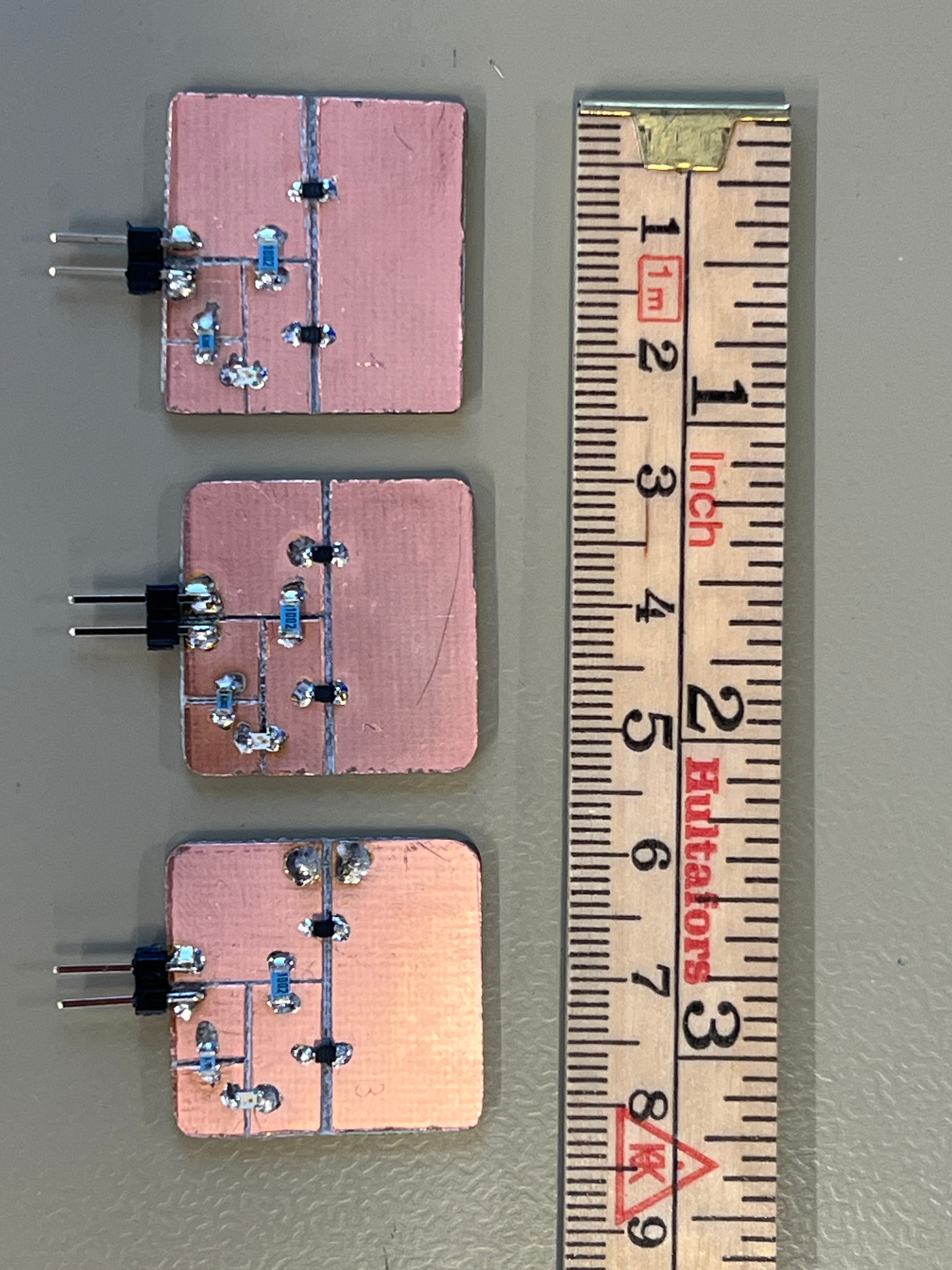
I have soldered together a couple of units based on the latest video in the series, on an etched copper plate.
When I have a piece of copper tape over a button on the 3300 panel, I can touch the tape to activate the button, capacitive touch works through and across the tape.
The moment I stick on the module however, it more or less (tests with loose bits of tape and large fingers can be somewhat tough to reliably reproduce) doesn’t react to my finger at all. Tapping the tape over the button, the tape bridging the gap, the tape on the module, nothing.
If I tap the tape WITH the module itself as I hold it, it will only activate if I hold across the copper of the module, bypassing the circuit, but if I hold on the in-out pins of the module, it more or less never activates from a tap.
I tried wiring the module up to GND and digital pin 5 on an Arduino UNO R4, which I plugged via usb-c to the wall. Running the code:
void loop() {
  pinMode(triggerPin, OUTPUT);
  digitalWrite(triggerPin, HIGH);
  delay(350);
  pinMode(triggerPin, INPUT);
  delay(3000);
}
The LED on the module blinks just fine, but it does absolutely nothing to trigger any manner of capacitive touch, and this has been tried with various lengths and widths of copper tape. With conductive adhesive, of course, 3M #1181.
Is the parasitic capacitance of the circuit/PCB as a whole too high, making the 3300 simply ignore the input, or not register it? I have 3 modules, all of which I’m pretty sure I soldered correctly, and again, LED activates on all of them just fine.
Any and all help would be appreciated! I would LOVE for this to work!