About 5 years ago I made this video:
I have toyed with the idea of doing an update on this project, to make it into something that others could build easily.
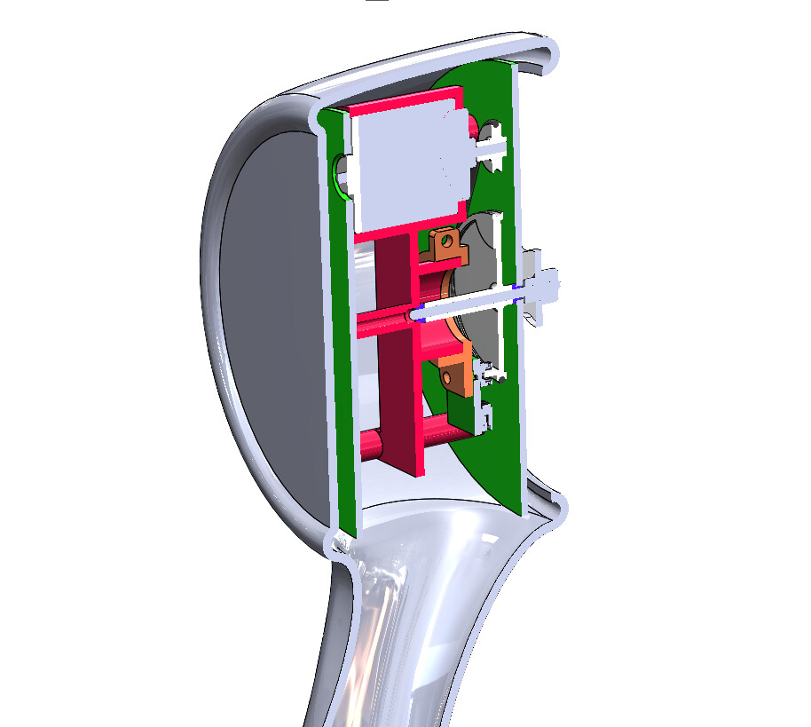
I have noodled around in CAD a bit considering how this could work, I cooked up an idea for a design that uses 3 PCB’s - Main Board, Rotor, and Display Board.
The housing and a few internal parts would be 3D printed.
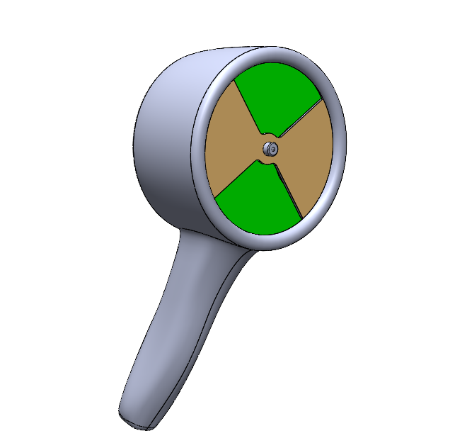
Display and UI are still TBD- The original prototype just uses a bunch of RGB LED’s
as a simple bi-color bar graph display - RED for positive voltages and GREEN for negative.
The rotor and main analog board PCB’s could get gold plated for sexy factor!
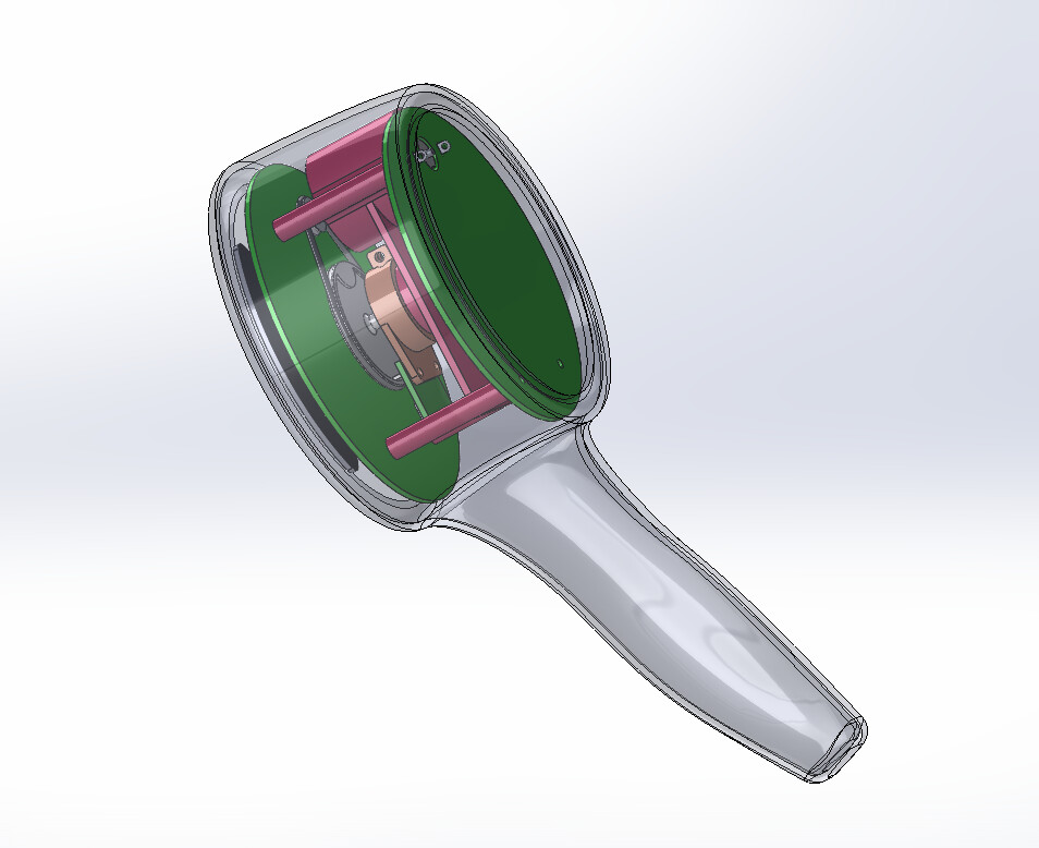
A belt drive from a small brushed DC motor spins the rotor.
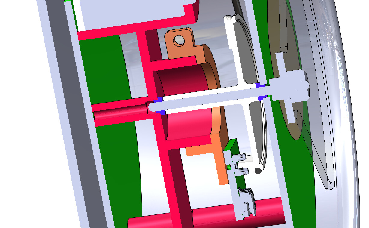
A flag on the pully creates the angular phase reference via a slotted optical switch.
The mount for the switch can be adjusted to get the phasing perfect - while it’s running.
One tricky thing is to prevent any charges from accumulating on the surfaces of the housing or the rotor- this is not trivial if the housing is plastic- maybe we need to print the housing in conductive plastic?
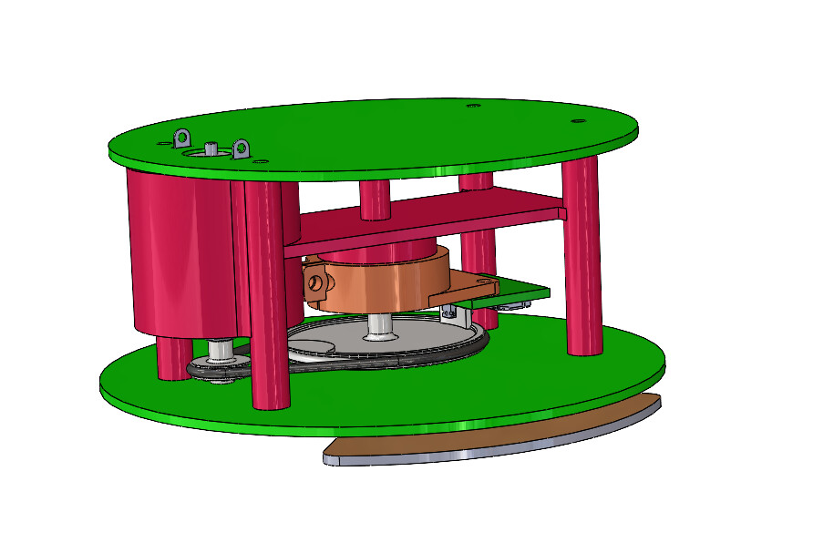
The hollow section of the red bracket would contain a small compression spring and a graphite rod (pencil lead) that would be lightly preloaded against the rounded end of the rotor shaft, the spring rests on a grounded pad on the display PCB to keep the rotor at ground.
This setup acts as a low-friction grounding brush.
Any electric charge on or near the rotor totally kills the function, the external signal gets totally swamped by the field. I learned this building the first one, without the grounding brush, it goes haywire.
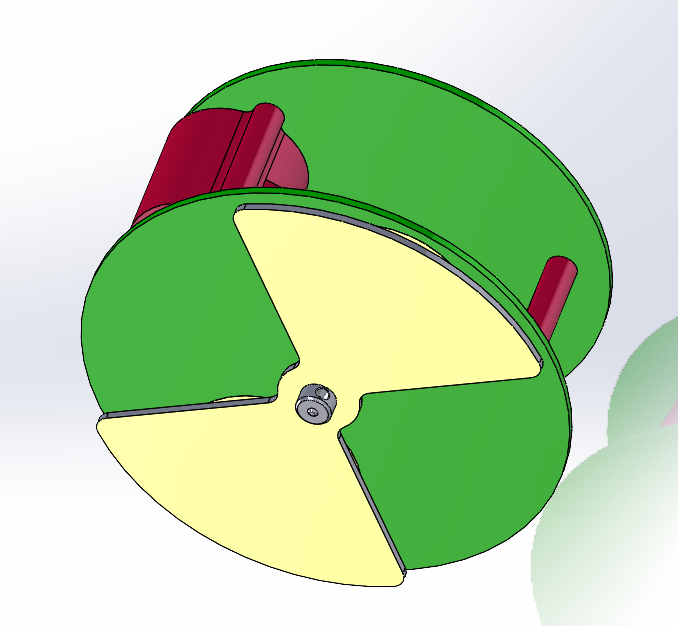
The first tests would need to validate the idea of a PCB rotor.
The bare edges of the PCB might hold enough charge to make it not function correctly?
Maybe a bit of conductive paint could fix this?
Some other thoughts:
Add a distance sensor, or some parallax lasers to position the head at a known distance- so the actual surface voltage can be determined?
Display and UI? what would be cool and most practical?
Batteries? Internal LiPo or AA cells?
External Power? a jack to plug in some external source? USB power?
For sure a 1/4”-20 female thread somewhere so you can stick it on a tripod?
Data output? via what means? What format?
The GND reference? a banana jack?
Let me know if you have any other ideas- and PLEASE VOTE for your favorite project idea!