Icosahedron LED Lamp Challenge

Icosahedron LED Lamp Challenge

The Problem & Concept

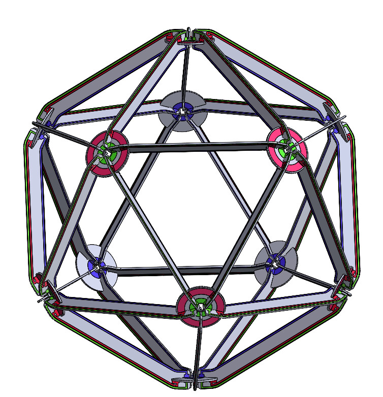
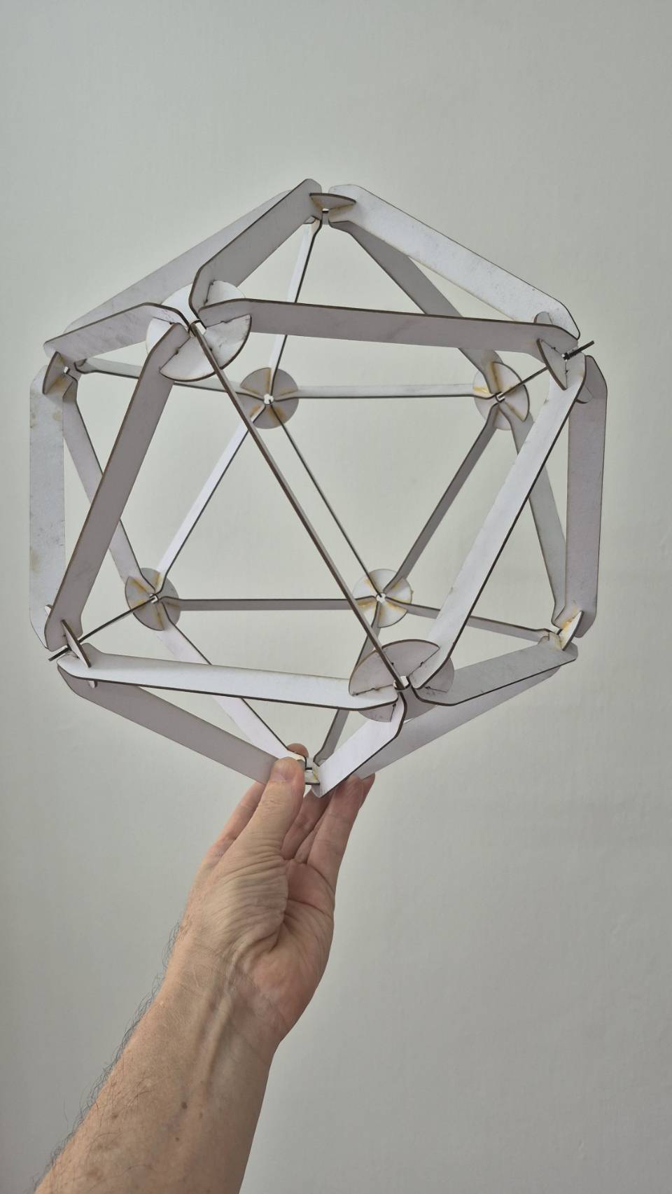
This module creates a flat-pack, self-assembly LED lamp kit that forms a strong, three-dimensional icosahedron. The use case is an elegant, user-assembled light fixture that requires only a 12V power wire and features a gesture-based dimming interface.

Leo's Rough Design

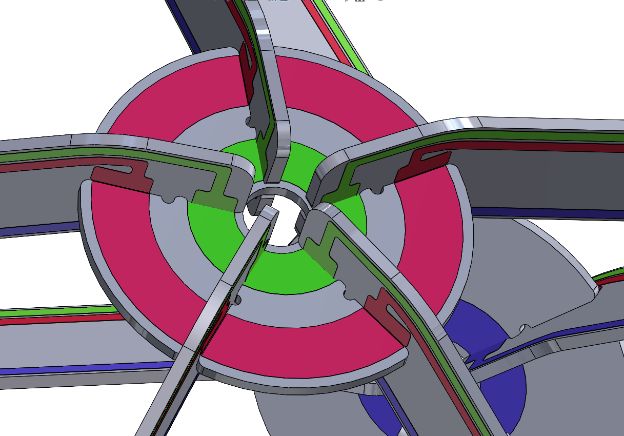
  • Circuit Approach: Double-sided PCB spars and hubs form the structure. Three conductors are used throughout: 12V, Ground, and a common PWM signal for all LEDs.
  • Key Components:
    • LEDs: Warm white LEDs, 3.2V forward voltage. Three LEDs in series per stack, with two stacks per side of a spar (6 LEDs per side, 12 per spar).
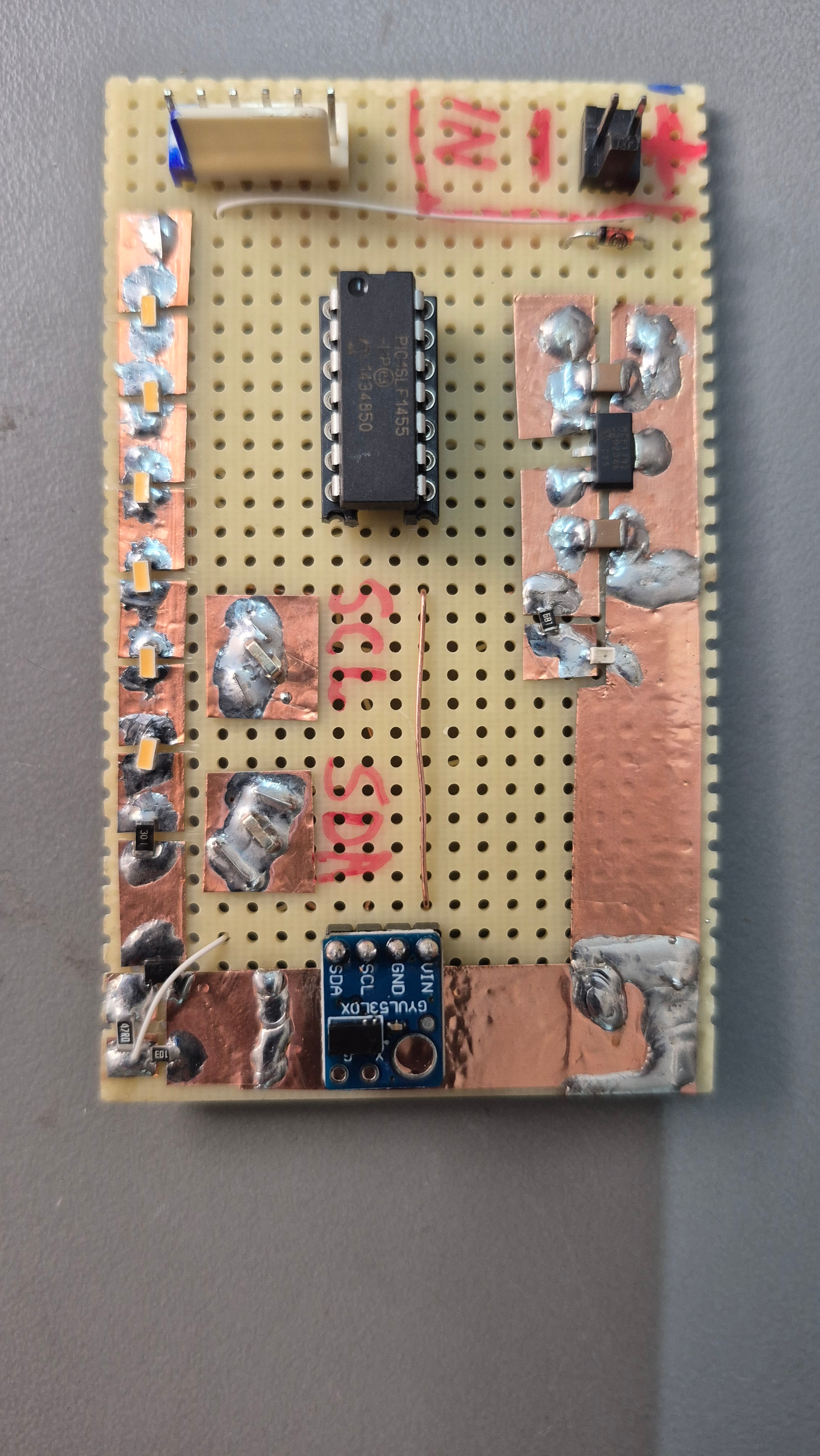
    • Power & Control: 12V design voltage. A single N-channel MOSFET on the "brain" hub controls the common PWM connection for all LED strings.
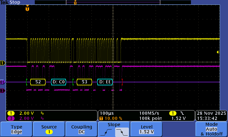
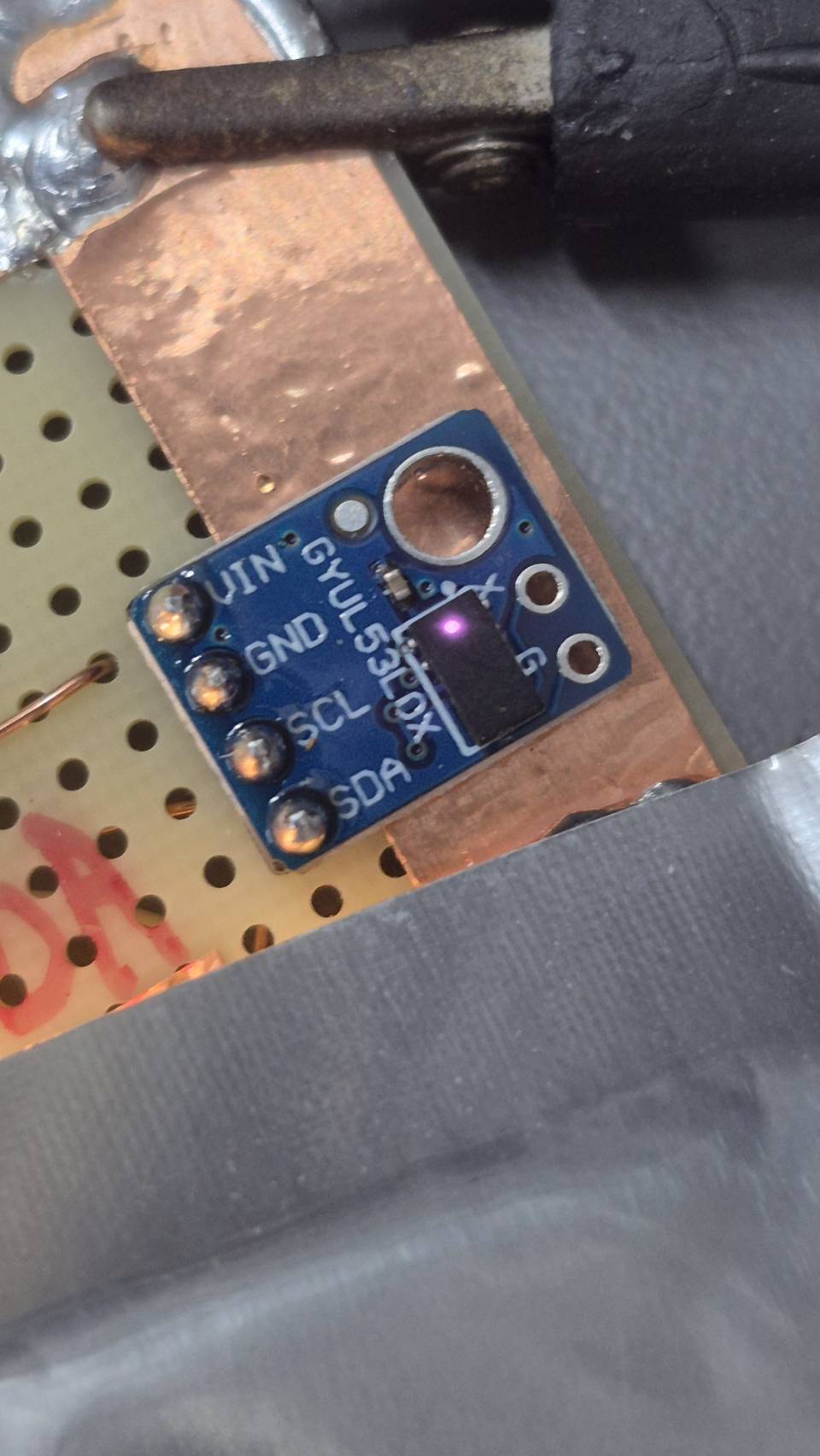
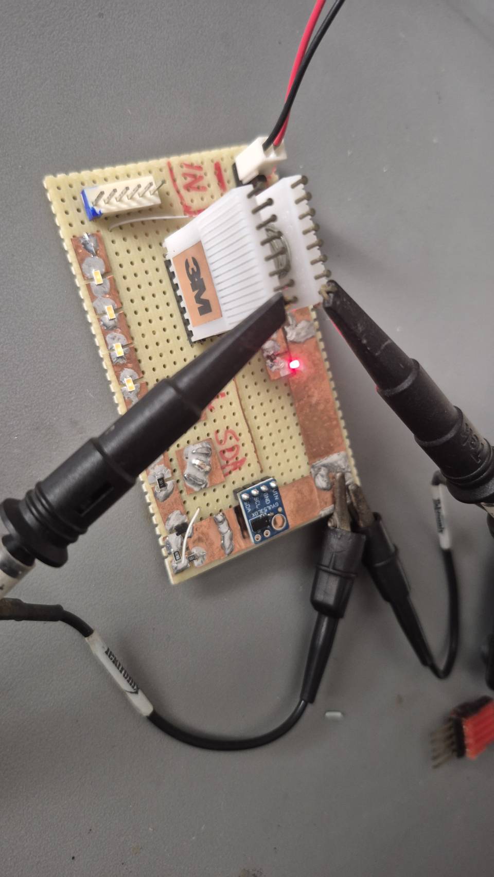
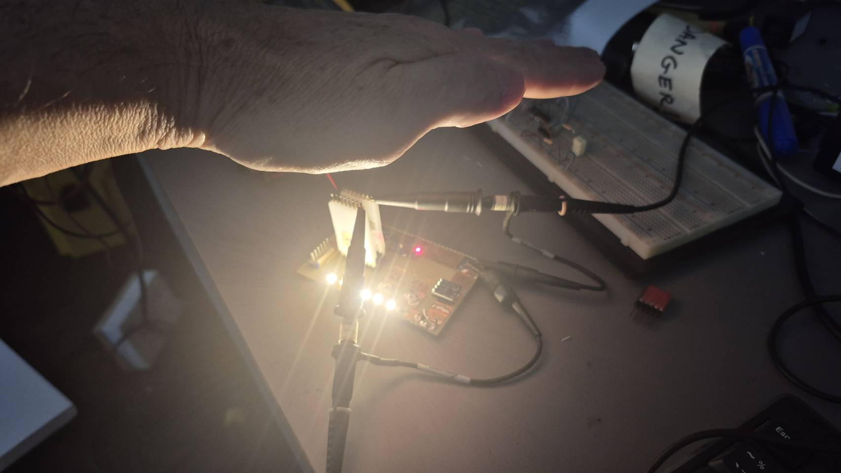
    • MCU & Sensor: Microcontroller and a VL53L0X time-of-flight distance sensor on the "brain" hub for gesture control.
  • Mechanical Design:
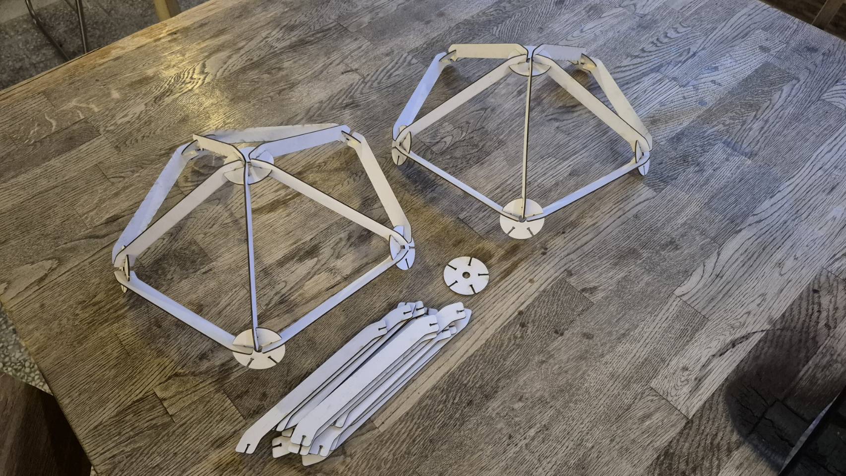
    • The icosahedron is constructed from identical PCB spars and ten identical PCB hubs, plus two specialized hubs (top for power, bottom for the brain).
    • Parts are designed to be router-cut from 1/16th inch PCB material, with slots modified for router-based PCB fabrication.
    • Mechanical and electrical connections are made simultaneously by soldering fillets onto tinned lands/rings at the hub-spar junctions.
  • Specifications:
    • Total LEDs: 360 (30 spars * 12 LEDs each).
    • Current per spar: 60mA.
    • Total current: ~1.8A.
    • Total power: ~21.6W.

Design Challenge #1: Gesture-Controlled, Flat-Pack PCB Lamp

  • How feasible is the redundant 3-conductor electrical connection scheme, and what are the potential failure modes of relying on hand-soldered joints for both structure and connectivity?
  • What improvements could be made to the spar and hub mechanical design to ensure robust assembly and alignment for a first-time user with only a soldering iron?
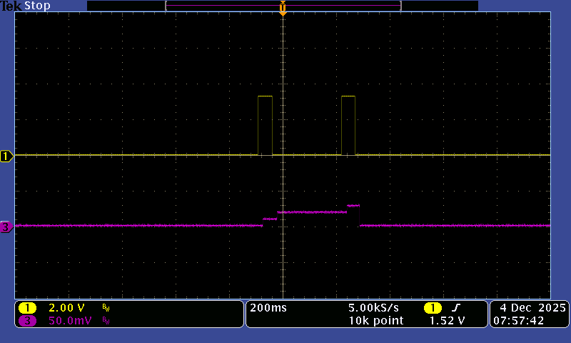
  • How reliable is the VL53L0X sensor for this gesture interface, and what are the weak points (e.g., ambient light interference, multiple sensor crosstalk) that need to be mitigated in the final design?
  • Is the proposed power distribution (carrying ~1.8A total through soldered PCB traces and joints) robust enough, or are there potential bottlenecks for voltage drop or heating?
  • What user experience challenges might arise during the assembly process, and how can the design be modified to make it more intuitive and mistake-proof?
  • What key elements are missing from the initial concept, such as thermal management for the LEDs, strain relief for the power cable, or a programming/debugging interface for the MCU?
  • How could the Gesture Input concept be improved?

Re. sensor interference, if this was an issue you could add shrouding so it only looked directly downwards, though you’d need to check if reflections from the shroud walls are an issue. There are quite a few of these sensors from various manufacturers nowadays so shouldn’t be hard to find something suitable. Might even be doable with a simple cheaper strength-of-reflection system as you only care about changes, not absolute values. That may give you more choice of field of view

I’m wondering if it might be possible to do it with only 2 interconnect wires - as the structure is quite sparse, you could maybe have the sensor at the top, looking through. You need a sensor that either isn’t confused by reflections from the inside bottom, or gives multiple outputs for each “target” or can be programmed to ignore early reflections. Ultrasonic may work here but it’s bigger and more likely to have interference issues.
Or maybe have a ring opening at the bottom. Having the control at the top would also be less visible.

Alternatively you could use a system like I used a while ago to do sensing over the same 2 wires supplying the LEDs https://www.youtube.com/watch?v=8WH5tCNIIck
As you don’t have a long cable you could use a significantly higher PWM frequency to reduce flicker.

You’d have the main control MCU at the top and a tiny MCU/sensor at the bottom. Something like the 8-pin CH32V003 would be a nice cheap solution. For bonus points, both MCUs could have the same firmware, and determine their role based on a pin being pulled high/low by the PCB,

If you can get it to 2 wires then you simplify the joint as you can just use top & bottom, so soldering is much easier

Another enhancement could be some local communications such that dimming one light also dims others. Perhaps some gesture to distinguish if you want to do one or both. Maybe IR vs. radio so it is only limited to the same room.

An alternative to soldering could be spring contacts and a click-together detail, or plastic rivets and 3D printed brackets. Not having to solder would increase the appeal - you could perhaps do it in a way that allows a solder and a non-solder version using the same PCBs, just not fitting the spring contacts.

I’d probably go 24 vs. 12V, to reduce current and allow a thinner/longer drop wire.

A little update.

I have been ordering parts and gathering materials for the project.
Also exploring the CAD design, working on refining the structure a bit more, fixing up the joint slot details and slimming the spars down. I currently imagine a 3 X 5 Spar cracker PCB (make 2 each for 30 spars) and a 3 X 4 cracker PCB for the Hub disks. (parts on one side)

24 volts is a good idea- this halves the overall current, reducing voltage drops etc. And I have so many 24 Volt power supplies in my stock already.

A good bit of the upcoming experimentation will be around evaluating the distance sensor, to see how solid it is under varying conditions. I have never actually used this VL53L0X part, but it looks promising from what I have seen in random Youtube videos.

For the micro- I am very comfortable with the PICs, I am considering the PIC16LF1575 in the UQFN-16 package, it’s got a nice 16 bit PWM engine, I can generate a nice fast PWM and gamma correct it via a lookup table in ROM to make the dimming really smooth and creamy.

The CH32V003 is very interesting- and probably much cheaper than the PIC?- how are the DEV tools for this part? That’s a big consideration.

With this very sparse physical structure, I don’t have a lot of room for big bulk bypass capacitors, which are needed to reduce the current ripple on the power input line.
One idea is to distribute these caps over the entire structure- on each spar.
Small MLCC (ceramic) caps are good, but I have to be careful to avoid the strange effect where MLCC’s make audible noise. (piezo effects) I think if I stick to small value caps, this effect can be largely avoided.

1 Like

CH32V003 tools - the manufacturer’s “Mounriver studio” is OK if you ignore their bloated HAL stuff. There is also CNLohr’s CH32fun open source setup. Programmers are very cheap (WCH Link-E $5 on Aliexpress), and there is a standalone programmer WCH-MCU-DL for production for $20 )
For PICs there are also several 8-pin devices in SO or DFN, e.g. 16F15313 - most have 10 bit PWM but you can extend this easily with dithering. There’s also the newer 16F13113 with configurable logic block that could implement higher-res PWM in hardware.
To avoid MLCC noise and reduce the needed capacitance you could use dithered PWM over 20Khz so it’s not audible.

Now you have piqued my curiosity! what is “Dithered PWM”? It must be similar to “scrambled PWM”? (Mackroblock LED drivers) And how would I go about implementing this in a simple micro?
The higher PWM frequency also reduces the size of the bulk bypass capacitor required!
A double-win there.

PWM is always a trade-off between frequency and resolution, we want to avoid flicker, yet have as many bits of resolution available to give us the best visual dynamic range.
For example- a 16Mhz clock feeding a 16 bit counter gives us a PWM frequency of 244 Hz, not terrible, but you can still kind of ‘feel’ the flicker, especially if you move your head quickly.

Lower counter resolutions produce higher PWM frequencies, but at the expense of poor low-end brightness control. (chunky steps, not smooth, even dimming)

The worst is when you end up with a PWM frequency around 2Khz, at this frequency, your ears are super sensitive and it’s almost impossible to avoid SOME audible singing, which is NOT what you want from a light fixture.

Super easy, yes very similar to ES-PWM or Scrambled PWM.
For simplicity say you have 8 bits hardware PWM and you want 16 bits.
You effectively spread the lowest 8 bits evenly over 256 hardware cycles by extending the hardware PWM by one count.
Your fundamental PWM frequency can be above audible, and you have a lower frequency “ripple” on that which is too small to be visible, and doesn’t contribute to any audible effect. It also allows a lower PWM clock.

e.g. for 0x180, half the hardware cycles are extended, so your PWM values are 1,2,1,2 etc.
For 0x140, it’s 1,2,1,1 etc.

This is extremely easy to code - you set your hardware PWM to the upper byte of the 16-bit PWM value, and on each hardware PWM cycle you add the lower byte of the PWM value to an 8-bit accumulator. If there is a carry, you increase the hardware PWM by 1. On the 8 bit PICs, there is a neat hack you can do in C by reading the hardware carry flag register after an addition, so you end up just 2 lines:

PWMacc+=PWMlo;
If (CARRY) PWM5DCH=PWMhi+1; else PWM5DCH=PWMhi;

e.g. for 4MHz PWM clock with 8 bit hardware, your fundamental is 16Khz, and your worst-case ripple is 0.4% at 62.5Hz.In practice, 14 bits are more than enough so your worst-case ripple is at 240Hz. In practice you use 10 bit hardware if available, I’ll dig out some PIC code for this later.

This and other things are discussed in a talk I gave at Hackaday a while ago “Everything I’ve Learnt About LEDs” : https://www.youtube.com/live/5SQt1f4PsRU?si=osyieVRa9Qgkqt-D

I watched your very comprehensive video presentation, a goldmine of tips and tricks for those interested in LED control/drive techniques.

The dithered PWM concept is simpler than I imagined- but doesn’t this mean that my ISR (Interrupt Service Routine) needs to run at the same rate as the PWM frequency?

This will be quite a bit of overhead, the example you gave using a 4Mhz clock with an 8-bit hardware PWM engine results in a PWM frequency of 15.625 Khz, or every 64 uS.

We end up dithering the PWM value +1 or +0 at a cyclic sub-frequency that averages out- emulating a higher PWM resolution- Do I have this idea right?

As long as the ISR is tight and well optimized, this should work fine.

In this lamp example, I would poll the I2C routine communicating with the distance sensor, leaving the interrupt system to manage the PWM dithering.

The “engine” that will manage the gesture interface concept can be interrupted without issue, there is nothing timing critical going on there.

Yes the ISR runs at the PWM frequency, but is doing very little, and the MCU isn’t going to need to do much else at the same time - even if the ISR sucks 80% of the CPU, there’s still plenty to read the sensor to decide what brightness is needed. I2C can be in hardware so not an issue if response is slowed a bit by the ISR, though even bit-banked I2C is not timing sensitive as it’s synchronous, though would be slower than hardware.

Here’s some actual code - this is for the 16F15313, but most (later) PICs have similar PWM peripherals, the interrupt code is about 30 instructions, so on a PIC running 16MHz, =250nS instruction time, under 10uS including interrupt entry/exit.

(This was pulled from an application that actually ran the PWM as a polled foreground task, as it needed fast int response for serial comms)

volatile u16 wval; // this is your 16 bit PWM value

Initialisation :

T2CLKCON = 1; //osc/4
T2CON = 0x80;
PR2 = 0xff;

PWM4CON = 0x80;
RA4PPS = 0x0C; // Set RA4 as PWM out

Timer 2 interrupt :

static u8 wsub;
u16 i;

i = wval; // bit 15..6 = hardware, 5..0 = subPWM
wsub += ((wval & 0x3F) << 2); // add 6 bit subPWM to accumulator
if (CARRY) {
i += 0x40; // increment LS bit of 10-bit hardware
if (CARRY) i -= 0x40; // avoid overflow at top end
}
PWM4DCH = i >> 8; // only top two bits used by hardware
PWM4DCL = (u8) i;

This is great, thanks for the code.

I will implement this idea as a learning experience.

Getting a rough breadboard together now. It’s a hybrid of SMD and a DIP MCU.

Supply voltage will be 24 volts. The stack of 6 white LEDs are all in series here - representing one LED spar.

Installed an integrated distance sensor module, this module has junk on it that I do not need, but perhaps it’s ubiquity will win the day? It will just barely fit at the bottom of the lamp as it is. The bare sensor is much smaller, but i fear it will be a pain to actually obtain the bare sensors?

Next step is to get the sensor running. I will try is to drive the PWM engine directly from the sensor data, this is a good way to visualize what it’s doing in real time.

Once this works, I will start to develop the control algorithm.

1 Like

Progress!

Got the MCU to read a register in the distance sensor correctly via the I2C interface.
Got the basic PWM working - great steps!

I am exploring the whole idea of using ChatGPT to help me code, it’s clearly more productive than just doing it the “old way” - pouring endlessly over datasheets, writing everything by hand…

But… it requires a very different mindset:
At first i tried to obsess over the perfect prompt that would get me a working program, (imagine how that went?) now I try to use it only to make function blocks, I give it the general overview of what I am doing, (context) but focus on “keeping things on the rails” by just asking for one piece at a time, testing each piece before moving on.

Sometimes I can feel Chatgpt going loopy, It starts suggesting that I rearchitect things that should not be touched, but my new approach prevents it from going totally haywire, I remain in control.

It’s starting to feel like a human.

1 Like

Been working on the firmware the last few days, it’s almost there, a few more tweaks.

It’s been a lot more difficult than I first imagined, (big surprise?)
The VL53L0X sensor is an amazing piece of kit, and unsurprisingly, it’s extremely complex under the hood. I finally got Chatgpt to port a Pololu Arduino library over to the PIC which allowed me to get the sensor running at 50Hz update rate with reasonable stability.

This forum post from the ST micro support page gives you an inkling to what nightmares await those who dare to dive deeper into this thing:

Getting it to “work” was not that hard, but getting it to give me what I need for THIS project took a day and a half of fiddling.

I am going for a “No Reserve” design here, trying to use all the stuff I have learned to make this perform the best I can muster.

Here is a rough overview of the software architecture:

(all running on a 16 Mhz PIC16LF1455 part)

(1) A polled VL53L0X sensor routine giving me distance readings every 20 mS over the I2C interface. (measuring how far my hand is from the bottom of the lamp)

(2) A 16 bit, 15 Khz PWM engine using the 10 Bit internal hardware, extended to 16 bits via dithering, which is handled by an interrupt routine that runs at the PWM rate. (special thanks to Mikeselectricstuff) This eats almost 50% of the CPU bandwidth! (as measured with an IO pin triggered by the ISR)
This works great, absolutely no visible flicker, and enough resolution for deep, creamy dimming.

(3) Visual brightness correction (Gamma correction) via 512 level LUT (look-up-table)
This maps a 10 bit input to a 16 bit output for the PWM engine.
This system compensates for the human eyes non-linear response to light intensity, it helps the low-end light levels look smooth and more linear. (Warning: do not use AI to generate the LUT values, it’s hopeless at this task)

(4) A ramping engine that prevents sudden, jerky changes in light level.
It uses TIMER1 to pace the rate-of-change, the light level ramps smoothly to the new commanded value, without jumps, glitches or flashes.

(5) A state machine that interprets the input gestures, to recognize the commands to toggle the lamp on-off, and to handle dimming.

(6) A first-in, last-out delay filter.
This revolving buffer helps to solve a dumb problem- When you arrive at the brightness level you want, and pull your hand away, the last reading you get from the sensor is not very good, it’s when your hand just leaves the sensing beam. The solution is to detect the hand leaving the beam, then use a good sample from 100 mS ago to set the brightness.

This all ends up being a big wad of code for such a simple thing?

Some additional thoughts:

Since the PICKIT5 programmer and debugger uses the same pins as the I2C engine, I cannot run the debugger on the actual hardware- this is REALLY frustrating, I had to use a lot of old-school tricks to debug. (the pullup resistors on the I2C line make the debugger unhappy.)

I setup another chip on a breadboard, without the pullups, this was good for debugging the PWM stuff- without the sensor input.

I also found that the chip has a DAC on board, it’s only 5 bits, but this was actually perfect to output the current state of the gesture state machine, allowing me to see exactly how it’s processing the sensor input - in real-time.

The image below shows the “hand present” signal (IO pin output) and the DAC output on the lower trace, showing the state machine stepping through as it processes an input gesture:

This was a life-saver for debugging the gesture interface!

Driving the LED’s - wrestling with the usual conundrum:

The distance sensor runs on 3.3V, so naturally, one would also use a 3.3V MCU.
Now, keeping things simple, we need to drive a MOSFET gate from this 3.3V IO pin.
Finding an FET that can handle an amp while being driven from 3.3 V is doable, but its not going to be very fast. The IO pin has to drive the large gate capacitance, it’s limited source and sink current makes it rather slow.

Now with 16 Bit, 15 Khz PWM, if we really want those low value steps to look great, we need to have very fast switching, otherwise the LED will not light at all with really low duty cycle values - the pulses are too narrow to get the FET to turn on.

So how do we speed this up? gate driver? sure- but there are no 3.3V gate driver chips.
I could add a 2nd voltage regulator, allowing me to use a 5V gate driver, but uhhhng! it’s getting messy!

Now I am working on getting my laser cutter up and running- I want to make some quick cardboard mockups to experiment with assembly and general aesthetics, then it’s on to PCB design.

Nice one!

That’s a really good breakdown of the different parts.

As for it being over complicated, I don’t think so: it’s just coherent.

I remember as a teenager reading about someone commenting on a toaster design using a 4-bit microcontroller to do the timing and claiming it was “simple”. I didn’t have enough experience to know if they were joking or not (“a whole microprocessor? Just for a toaster? Toasters don’t need micros: clockwork is much simpler!”) and, now that I do have the experience, I judge them to have been not only serious, but correct: that’s just the design language of these digital systems.

And now, looking from the other side, it’s so rare to see an engineer who can break down a “simple” system into “simple” parts and keep it all coherent. I think your ability to do that so clearly and elegantly is what I like about your projects and your engineering style.

Anyway, regarding the I2C vs Debugger thing. I tend to use AVRs and their programming port is shared with the SPI bus so I’ve successfully used the approach mentioned here 4.1.1 Shared Use of SPI Programming Lines to allow both to be used in circuit at the same time. SPI has pullups too so perhaps something similar will work for the PIC’s I2C pins?

Diodes Inc DGD0215 (or 0216) needs a supply voltage between 4.5V and 18V but it has an internal reference for the logic drive so the logic 1 threshold is 2.4V min and the logic 0 is 0.8V max.

The PIC16LF1455 datasheet (pg 351) says the Output Low Voltage is 0.6V max and the Output High Voltage is Vdd-0.7 Min (2.6V @ 3.3V).

So perhaps you could power it from the LED power supply and it would work with a 3.3V logic drive from the PIC?

I’ve never used these gate drivers, just had a quick peek at the datasheet.

A gate driver seems like a must, the LED voltage (24V) is at the limit for max gate voltage.
Probably need a 5V and 3.3V regulator. The 3.3 regulator can be cascaded off the 5V for lower power dissipation. (smaller part)

I will explore this idea tomorrow.

I really don’t think you need a gate driver - 1A is nothing for a MOSFET - a little SOT-23 will do this fine - you don’t want to over-beef it as the gate capacitance will be higher. If you get linearity issues with very short pulses, fix it in the gamma lookup table. If anything I tend to end up with 1-10K in series with the gate to soften the turn-on to reduce noise.As I2C is open-drain, you could potentially run the PIC at 5V for higher MOSFET drive, with the sensor and I2C pullups to +3.3v

Btw I almost never find the need for a debugger - a fast UART (1-4Mbaud) spitting out data and ‘scope serial decode, plus some simple IO pins to flag things like when you’re in an interrupt is usually more than enough.

The 16LF1454 is a 13-year old part, there is no reason to use something that old when there are much better and cheaper parts available. e.g. 16F1532x series.
A major benefit of these is that pretty much any pin can map to any peripheral, which makes PCB layout a lot simpler. If you need a little more MOSFET drive, you can use this programmable pin mapping to route the same PWM output to multiple pins, which you can connect in parallel for more drive strength.

There are also multiple pin-count variants, so you can use one with a higher pin count for development to allow plenty of debug outputs. Also nice stuff like dual UARTs, and the CLC perpiheral that can do simple logic gating functions in hardware.

And I2C is on different pins to the programmer/debugger!

Fired up the laser cutter and made a mockup out of 1.5 mm cardboard.
Just glued the pieces together with wood glue- pretending it was solder.

Getting “real” with mockups like this is really important, gets you out of CAD mentality, where everything is perfect and scale has no meaning.

The assembly process is pretty simple, I imagine soldering the parts together will be rather satisfying! almost instant results without waiting for glue to dry.

What is amazing is how stiff and strong this geometry is, even with wonky cardboard as the material.

I think the whole lamp can be boiled down to 2 cracker boards:

(a) a 12 - up hub board, with 3 rows of 4 hubs on a breakaway PCB.
This board would have SMD parts on one side only, and only on 1 of the 12 hubs.

(b) a 10 - up spar board with SMD LEDs on both sides.
You make 3 of these to complete the lamp. (30 total spars)

It would be smart to have the rectangular ‘frame board’ designed so you could test a whole set of 10 spars at once by applying 24 volts to 2 large, well marked pads, with traces routed through the breakaway tabs. if they all light up, you are good.

I am using the PIC16F1455 mostly because I have these in stock!

Your idea of using a part with remappable pins to increase the drive by paralleling outputs is very clever! That might be the ticket here.

If I change my system voltage to 5V and use a sensor module (containing it’s own LDO regulator and level shifters) I could keep the BOM very minimal.

Now I am using a Toshiba SSM3K341R N-FET to drive the LEDs.
RDS-on is around 70 milliohms at 3.3V, but we pay for this with 550 pF input capacitance.

I have experimented with adding an offset to the gamma table to correct for this switching delay, it’s workable up to a point, but when we dither at low values, the nuance is lost.

Diodes DMG2302 - 70mR at 2.5V, 130pF. 20V rating but the Vf of the LEDs means it will only see about 6V.

Chinese versions for about half a cent

There is also a cheaper (and apparently better documented) sensor from Osram that maybe worth a look TMF8805-1BM OLGA12 LF T&RDP ams-OSRAM USA INC. | Sensors, Transducers | DigiKey

Also this from Vishay - I think this uses signal strength rather than ToF - it may have significantly lower power draw, (=less heat in your regulator) though hard to tell as you need to work out what LED current needed for the range you want

An option could be to switch to a lower frequency conventional PWM at the very lowest end. Though by the time you’re that low you may as well just turn off!